Chapter 28 Diagnostics
General radiology viva advice#
In the FRCS (Tr & Orth) structured oral exam, most candidates will have anticipated the possibility of being asked a radiology topic and would have (wisely) prepared for this. While candidates will be asked bits and pieces of radiology during a topic discussion the assumption that a stand-alone 5-minute radiology topic is probably too much detailed knowledge for the average candidate (and examiner) to stretch out discussion for is wrong. We know candidates who have had very detailed questioning on the principles of either bone scans or MRI scanners lasting the full 5 minutes of a viva. Bone and MRI scanners would seem to be the most obvious questions that candidates would be asked, although a discussion about X-rays is also fair game. Sometimes, the examiner may put all of them in front of you (X-ray/ultrasound/CT/MRI/bone scan images) and give you a choice to speak on any one of them. A candidate scoring 6 would start to runout of steam at 3 minutes or struggle if they are seriously probed about the topic in detail. A bit depends on the examiner themselves on how much they really do understand the subject in depth, but you are gambling a bit with this one.
The other aspect of radiology which is extremely important and can certainly set you apart from the average candidate is to be able to describe radiographs, MRI and CT scans well. This is usually at the beginning of an oral question, so it is important to get off to a good start and describe the radiographic or
MRI features well. This is not always an easy skill to acquire, so our suggestion would be to arrange one or two tutorials from a local friendly radiologist who will be able to put you on the spot in describing various scans and radiographs. Going on a viva course, closely observing and making mental notes of how other candidates describe various radiographs is another way in which you can refine this technique. If all else fails, then practise out loud describing radiographs and scans from a book.
Structured oral examination question 1#
Radiographs
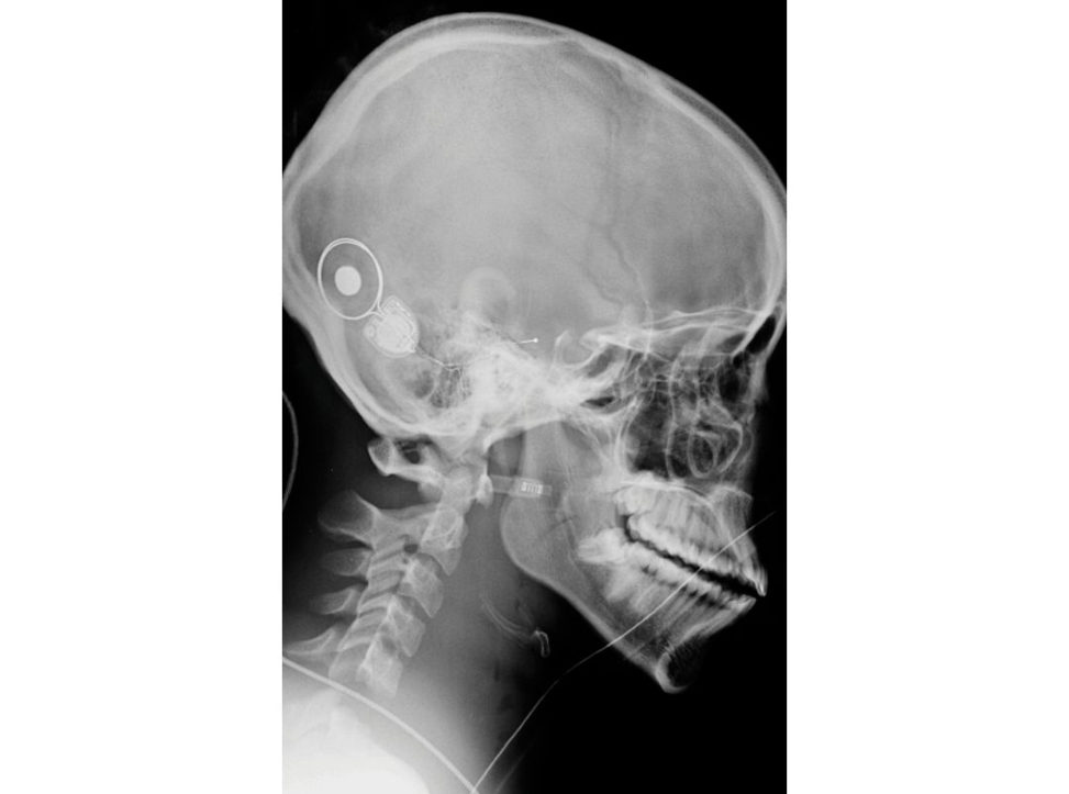
Figure 28.1a X-ray of cervical spine lateral (C5–6 dislocation).
What are X-rays?
X-rays are electromagnetic radiations of wavelength 15–0.01 nm.
How are X-rays generated?
X-rays are released on heating a fine tungsten filament to around 2200°C in a vacuum.1 Electrons travelling from the filament (cathode) to the target (anode) convert a small percentage (1%) of their kinetic energy into X-ray photons (by the formation of Bremsstrahlung and characteristic radiation). Bremsstrahlung interactions, the primary source of X-ray photons from an X-ray tube, are produced by the sudden stopping, breaking or slowing of high-speed electrons at the target. When the electrons from the filament strike the tungsten target, X-ray photons are created if they either hit a target nucleus directly (rare) or their path takes them close to the nucleus. If a high-speed electron hits the nucleus of a target atom, all its kinetic energy is transformed into a single X-ray photon.
Most high-speed electrons have near or wide misses with the nuclei. In these interactions, a negatively charged high-speed electron is atir acted toward the positively charged nucleus and loses some of its velocity. This deceleration causes the electron to lose some kinetic energy, which is given off in the form of a photon. The closer the high-speed electron approaches the nuclei, the greater is the electrostatic a tir action on the electron the braking effect, and the greater the energy of the resulting Bremsstrahlung photon.
How does digital radiography work?
Digital radiography uses a phosphor compound detector plate instead of the conventional photographic emulsion film. The detector generates a digital image that can either be printed or sent to PACS (picture archiving and communication system).
What measures will you take to minimize radiation exposure to staff while using an image intensifier?
The main source of radiation for the surgeon and the team is the scattered radiation from the patient Measures to minimize the radiation exposure to staff are: TDS (time/dis tance/shielding) (1) COMMENT: In the radiation time exposure As Low as Reasonably Achievable (ALARA principle). (2) Distance: The inverse square law. The amount of scatter radiation is inversely proportional to the square of the distance from the X-ray source. The distance between the X-ray source and the patient should be maximized, i.e. keep the image intensifier as close to the pa tientas possible. (Staff to stay 1 m away from the X-ray source.) (3) Shielding: Lead aprons (0.25 mm thick), thyroid shields and protective goggles.
What is collimation?
Reduction in the size of the window through which the X-rays are emift ed leads to sharper radiographs as well as reduction in radiation dose.
What is the maximum safe dose of occupation-r elated radiation exposure?
The whole-body exposure of 20 mSv over a year is the maximum acceptable radiation dose (averaged over 5 years) (UNSCEAR, 2010).
What does the picture show and what is its use in theatre (Figure 28.1b)?
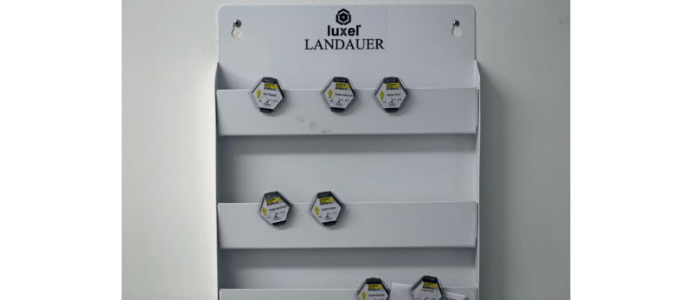
Figure 28.1b Dosimeter.
This shows a dosimeter. This is a device that measures exposure to ionizing radiation. It is used to estimate the radiation dose deposited in an individual wearing the device.
Anything else?
Ideally all orthopaedic surgeons should wear a personal radiation dosimeter This should be in a constant position beneath the protective lead gown to record any personal dose. If dose readings are too high then a review of theatre practice must take place. Dosimeters must be safely stored away from radiation sources and should never be shared. It is important to also take proper care of the lead apron. Crumpling of the lead apron will break the integrity of the lead fibre shielding. Lead aprons should be properly hung up after use and their integrity checked regularly. The answer could have been structured into discussion of radiation protection covering five areas: (1) minimization of radiation use, (2) maximizing the distance between the individual and the X-ray source, beam and scatter, (3) use of lead screens, (4) personal protective garments and (5) monitoring personal exposure dose. Additional notes: (1) Natural background radiation: 0.01 mS v/day (UK: 2.2 mSv/year). (2) Cosmic radiation during high-altitude flights : 0.001–0.01 mSv/hour. (3) X-ray chest: 0.1 mSv. (4) CT head: 1.5 mSv. (5) CT abdomen: 9.9 mSv equivalent to 500 chest X-rays. (6) X-rays were discovered by German scientist Wilhelm Roentgen in 1895.
(7) Lead aprons help in reducing the exposure by a factor of 4 in lateral view and a factor of 16 in posteroanterior view. Thyroid guards decrease the exposure 2.5 times the normal. E ye protection is essential and is the first determinant of workload in all procedures. Lead apron should have at least
0.5 mm equivalent thickness of lead and the goggles should be at least 0.15 mm lead equivalent thick.2
(8) Within 2 m of the C-Arm unit, lead protection is a must.
Structured oral examination question 2#
Ultrasound
What is ultrasound?
Ultrasound is a form of imaging that utilizes high-frequency sound waves to image interfaces between tissues with different acoustic properties (described as echo genic or hypoechoic). Fluid- filled tissues have low echogenicity while fat is highly echogenic.
What are the advantages of ultrasound?
Ultrasound is cheap, easily available, portable, non-invasive and dynamic. It is safer than CT as it does not emit ionizing radiation and unlike MRI can be used inpatients with cardiac pacemakers or metal clips.
And the disadvantages?
Its main disadvantage is that it is operator-dependent.
What is the physics behind ultrasound imaging?
The passage of electric current through a piezoelectric crystal causes deformation of the crystal surface, inturn producing sound waves. When the transducer is then applied to the patient’s skin using a lubricating jelly , these waves are then transmift ed into the patient body. The reflected waves when received back by the transducer cause distortion of the crystal surface, producing a voltage, which is then converted to an image. The duration between the sound wave emission and detection reflects the depth of the tissue beings tudied.1 The amount of energy reflected at the interface between tissues depends on the difference in acoustic impedance of those tissues. The acoustic impedance of a tissue is mainly determined by its density. Air has a much lower density than water or soft tissue, which inturn have a much lower density than bone. The larger the difference in acoustic impedance, the more energy will be reflected, and the brighter the resulting imag e.3 However, at the interface between soft tissue and air or bone, nearly all the w ave’s energy is reflected. No energy is transmift ed, and hence no information can be gained about tissues which lie deep to this point. This explains why ultrasound is generally not useful for assessment of bone, bowel or lung. It also explains why a coupling gel is required between the probe and patient skin to eliminate air.3 As a sound wave passes through the body it gradually loses its energy in a process called attenuation. Theca uses of attenuation are: absorption reflection, diffraction and refraction. Refraction causes a transmift ed wave to be deflected from its original course. Diffraction is scattering of the wave which occurs particularly when a w ave interacts with small structures. Most of attenuation however, occurs due to absorption. The energy of the sound wave is converted into friction between oscillating tissue particles and is lost in the form of heat. To compensate for this loss of energy, the ultrasound machine uses a process called time g ain compensation. This gives greater amplification to those echoes which take longer to return to the transducer, producing an even image.3
Frequency 3–50 MHz with a high-frequency probe used for deep tissues and a lo w-frequency probe for superficial tissues.
Tell me a few of the practical applications of ultrasound in orthopaedics.
A few uses of ultrasound in orthopaedics include: (1) Hip. a. Diagnosis and treatment monitoring in developmental dysplasia of the hip (the viva can drift to Graf’s classification of DDH from here). b. Detection and guided aspiration of hip effusion (especially in children). (2) Shoulder: To diagnose impingement and rotator cuff tears. (3) Tendons: To detect tendon ruptures, swelling/oedema (Achilles/tibialis posterior). (4) Soft -tissues welling – size, extent, solid or cystic ± guided biopsy. (5) Steroid/anaesthetic injections in to tender areas (plantar fasciitis), joints (subtalar/sub acromial) and around neuromas (Morton’s neuroma) (Figure 28.2). (6) Regional anaesthesia: Most of the distal limb surgeries are now done under awake-block anaesthesia (administered under ultrasound guidance).
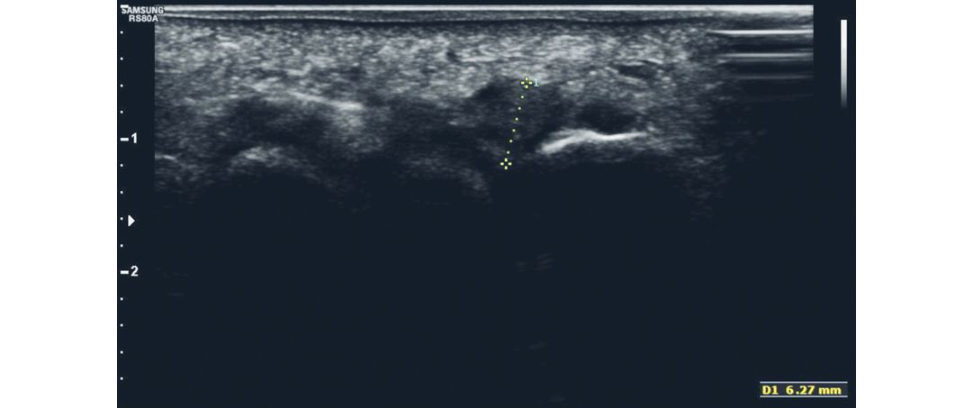
Figure 28.2 Ultrasound scan for interdigital neuroma.
Structured oral examination question 3#
CT scanners
How does a CT scanner work? What are the principles of a CT scanner?
The X-rays are liberated from the axially rotating X -ray tube. After passing through the patient they are received by a circle of stationary detectors. The data collected are processed by the computer and digital images are reconstructed. The scanning gantry rotates helically around the patient allowing continuous acquisition of data. With modern multi detector CT transverse (or axial) anatomical sections can be produced with high resolution and reformatted to create reconstructions in an y plane. The 3D CT scans allow better visualization of complex intra-articular fr acture/spinal problems but at the cost of slight loss of definition subtle fractures can fade away/be created). A recent additional feature is the ability to ‘ghost out’ structures, for example: a ghost outline of the femoral head can be maintained in cases of fractures of the acetabulum to show its relationship to the fracture and at the same time the acetabular fracture can be visualized more clearly. General information (1) CT was discovered by Sir Godfrey Hounsfield (Haye sUK) and the first patient brain scan was done in 1971. Sir Hounsfield was awarded the Joint Nobel prize (with Allan McLeod Cormack of Massachusetis) in 1979. (2) Hounsfield units are a measure of the attenuation coefficient of the tissue being scanned. (Bone = 1000 HU.) Bone windows are usually centred on 300 HU with a width of 1200 HU. (3) Limitations. a. Radiation dose. b. Artefact from orthopaedic metalware reduces image quality. c. Soft -tissue detail is limited.
Give some orthopaedic indications for CT scan.
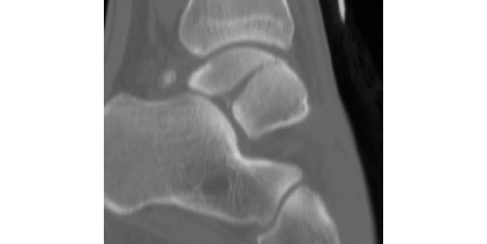
(1) Complex peri-articular fractures – for example, fractures of the acetabulum, tibial plafond, tibial plateau, proximal humerus, Lisfranc’s, talus, calcaneum and vertebrae. CT aids in planning incisions to minimize additional trauma to soft tissues ( Figure 28.3). (2) Polytrauma patients – head, chest and abdominal scanning (in about 30 seconds). (3) CT arthrography/myelography (if MRI is contraindicated). (4) Assessment of choice for non-union when radiographs are inconclusive: scaphoid. (5) Drilling/ablation of osteoid osteoma.
(6) Customized implants: CT scans are increasingly used for patien t-specific implants and instrumentation, especially for complex arthroplasty.
Figure 28.3 Sagift al reformatted image of ankle CT demonstrating t alar body fracture.
Structured oral examination question 4#
MRI scanners
Please describe the findings (Figure 26.4a,b)?
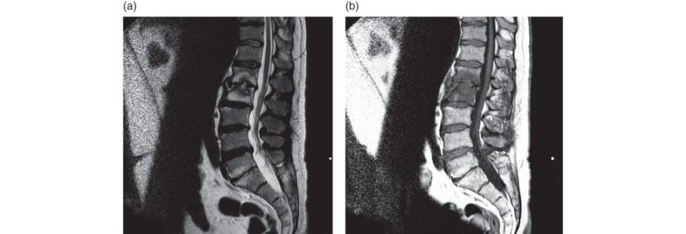
Figure 28.4 Sagift al T2 (a) and sagift al T1 (b) images of the lumbar spine. This demonstrates L1/2-disc space abnormality with adjacent endplate oedema. It could represent either disc space infection or acute inflammatory discovertebral lesion as might beseen in spondylitis.
This is an MRI scan of the lumbo-sacral spine of ... Dated ... Age ...
Is it a T1-weighted image or T2?
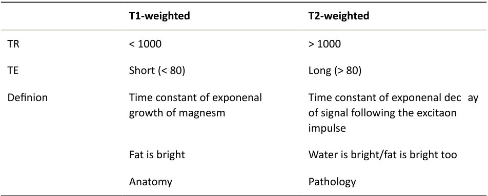
The image to the left is a T1 image as it has a TR (timet o repetion) value of (< 1000), whereas the image on the left is a T2 image (TR > 1000).4 (Don’t rely on fluid/fat signals forjudging the type, as they can be confusing in STIR or fat- suppressed images.) Most imaging protocols will use a combination of different sequences to optimally evaluate the structures and pathologies in question by providing both anatomical and pathological information. MRI can be utilize din any plane, and this is sometimes crucial in providing additional information.
What are the differences between T1 and T2 images?
What contrast is generally used with MRI?
Chelated gadolinium. It enhances the oedematous tissues on T1 image. An important but rare complication of gadolinium is nephrogenic systemic fibrosis (a fibrosing dermopathy), which has been reported to occur rarely inpatients with Stage 4 renal failure. Current guidance is that if the eGFR < 30, gadolinium should not be administered.
What are the contraindications for MRI scan?
(1) Implanted cardiac pacemaker and/or defibrillators. (2) Internal hearing aids/cochlear implants. (3) Implanted nerve stimula tors/dorsal column stimulators. (4) Metal objects in orbit of the eye. (5) Intracranial metal aneurysm clips. (6) Aortics tent graft. (7) Mechanical heart valve. Many coils, filters, coronary stents and gratis are made from non-ferromagnetic materials and MRI can be safely performed. They will require a pre-MRI check regarding their compatibility as some will demonstrate magnetic field interactions and are not safe with MRI use. MRI is usually used with extreme caution within the first 6 weeks postoperatively when any metallic clip (including skin clips) or implant has been utilize das they will not have become incorporated securely in tissues.
What else?
Certain types of intracranial aneurysm clips are an absolute contraindication to the use of MRI because excessive, magnetically induced forces can displace these clips and cause serious injury or death. Exposure of internal hearing aids to MRI may damage these components. In the case of cardiac pacemakers and defibrillators the MR environment can cause movement and heating of pacing leads temporary or permanent modification of the device, and deactivation of the device.
What are the advantages of MRI use?
MRI provides excellent soft tissue cont ast. It is particularly good for imaging tumours and occult fractures and does not involve using ionizing radiation.
What are the disadvantages of MRI use?
Patients may be claustrophobic, and it is not as good as CT for cortical bone imaging.
What are the indications for MR arthrograms?
(1) Shoulder: Suspected capsular/labral tears (Figure 28.4c). (2) Hip: Labral tears/Impingement. (3) Knee: Post-meniscectomy for recurrent tear. (4) Wrist: Scapholunate dissociation, TF CC tear, occult scaphoid fracture. (5) Ankle: Undisplaced osteochondral lesion of the talus.
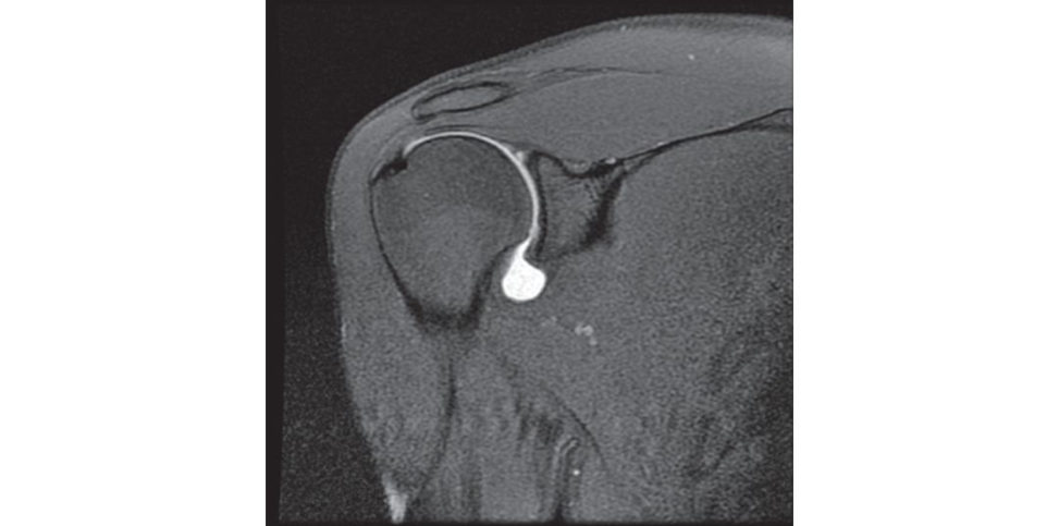
Figure 28.4c MRI arthrogram of shoulder demonstrating dye leakage from rotator cuff tear.
What is the basic principle of an MRI scanner?
The MRI scan involves exploiting the magne tic momen t/nuclear spin property of the hydrogen nucleus (in the tissues) when placed in ast rong magnetic field. Radio waves (64 MHz) are then applied using the transmift er coil. Following the cessation of the radio waves, the individual magnetic moments then precess and the response is recorded in the receiver coil. The frequency of precession depends on the strength of the external magnetic field. Larmor equation Frequency of precession = gyromagnetic ratio (constant) × strength of the external magnetic field
What do the terms PD, STIR and FATSAT sequences mean?
PD = Proton density-weighted image. It is commonly used in knee protocols to image the menisci.
FAT S AT and STIR are both sequences used to improve tissue contract by suppressing the response from fat in tissues.
FAT S AT : Abbreviation for fat saturation (spectral fat saturation). It can be applied to T1/T2/PD sequences.
T1 fat-saturated sequences are commonly used in MR arthrography and after the administration of contrast, and both PD and T2 fat-saturated sequences are commonly utilized to identify pathology.
STIR : Short tau inversion recovery. This is a very robust, commonly used sequence, which is very sensitive to abnormal fluid or oedema and so ordinarily demonstrates pathological processes well.
What is TE?
Time to echo. When a second radiofrequency pulse is applied after the first one is turned off, then the time duration between the first wave and the echo formation is termed TE. TE is used as a controllable factor as timing of application of the second radiofrequency pulse is at the discretion of the user.
What is extremity MRI?
Extremity MRI involves placement of only the involved extremity in the magnetic bore, while the rest of the body remains outside.5 Advantages are: (1) Reduced cost. (2) Improved patient comfort and reduced claustrophobia. (3) Facilitated siting. (4) Reduced patient risk. Disadvantage: only the distal two-thirds of the extremity can be scanned.
What is your option if the patient is claustrophobic in an MRI scanner?
Open MRI scanner ± sedation. Or consider alternative imaging modalities. Imaging artefacts 1. Chemical shift artefact: fat and water precess at different frequencies in the same external magnetic field. The f at image is slightly shifted with reference to the water image, hence low signal lines can sometimes beseen where these two are shifted away, or high signal lines can beseen where they overlap. These are generally easy to identify as they are generally found at the boundaries between fat and water. 2. Metal artefact: metal distorts the magnetic field causing major artefacts in its vicinity. T1- weighted images are less susceptible to metal artefacts than T2 images. Hence MARS (metal artefact reduction sequences) are commonly applied to study tissues around hip resurfacing implants.
3. Magic angle artefact: tendons normally yield low signals in all sequences due to low T2 relaxation times. However , if the collagen fibres of the tendon make an angle of 55° to the external magnetic field, the T2 relaxation time increases manyfold, causing a high signal on short echo time images This can be differentiated from tendinopathy by the 55° angle and the absence of a high signal on T2-weighted images.
Structured oral examination question 5#
Bone densitometry
What is bone densitometry?
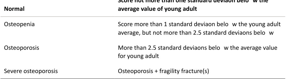
Bone densitometry, also called dual-energy X-ray absorptiome try or DEX Ascan, uses simultaneous measurement of the passage through the body of X-rays with two different energies. It uses a low dose of ionizing radiation and is accurate in diagnosing osteoporosis. The WHO guidelines for interpretation of bone densitometry results (T-score):
What are its uses?
The clinical applications of bone densitometry include: (1) Assessment of bone status in primary and secondary osteoporosis. (2) Assessment of the effect of treatment for osteoporosis. (3) Fracture risk assessment (what is FRAX score?). (4) Evaluation of preventive measure for bone loss associated with ageing/metabolic disorders. (5) Measure periprosthetic bone loss (particularly cementless hip arthroplasty).
OK. You have now started bisphosphonates on this patient for osteoporosis, how will you find out whether your treatment has been effective Will you repeat the bone density scan? When?
Repeated dual-energy X-ray absorptiome try (DX Ahas a high within- and between-patien t variability. The average annual increase in BM Din patients treated with alendronate is about 0.0085 g/cm2. This change is smaller than the typical year-to-year (within-person) BMD variation of 0.013 g/cm2. It would therefore be difficult to differentiate the medications effect from the random variation inherent in DX Ascans. Response is generally favourable after 3 years of treatment. While there is variation int est results from year to year, longer-term findings are more reliable. After 3 years of treatment, 97.5% of patients taking alendronate had an increase in hip BMD of at least 0.019 g/cm2, with a strong correlation between hip and spine measurements.
Hence, if needed I would repeat the bone density scan after 3 years, to evaluate efficacy of the treatment monitored in low–medium-risk patients The treatment of high-risk patients would need to be considered on an individual case basis.6,7
Name some techniques used to measure bone density in the axial skeleton? (The same question can be asked regarding appendicular skeleton.)
Techniques that can be used to measure bone density in axial skeleton are: (1) DEXA. Dual energy X-ray absorptiome try. (2) Quantitative CT (rarely used). (3) Quantitative MRI (rarely used).
Does DEXA measure true bone density or apparent? (A rather pointed question!)
DEXA measures apparent density (obviously) as it is a two-dimensional measurement quantified ing /cm2. Quantitative CT gives a volumetric (three-dimensional) true representation of bone density in g/cm3. Even quantitative CT can give false low readings as it also measures intravertebral fat.
Which of the bone density measurement techniques can differentiate between cortical and trabecular bone?
Quantitative CT and quantitative MRI.
What is FRAX score?
FRAX (Fracture Risk Assessment Tool) is the tool used to assess 10-year probability of hip/major osteoporotic fracture of patient sIt integrates clinical risk factors with bone mineral densitometry for femoral neck. Treatment for osteoporosis is recommended if the FRAX score for hip fracture is more than 3% or that for major osteoporosis-related fracture is more than 20% (National Osteoporosis Foundation 2008). 8,9
What is the Singh and Maini index for osteoporosis?10
The Singh index has been described on the basis of the presence/attenuation of various compressile/tensile trabeculae on a plain anteroposterior(AP) pelvis radiograph. Grade 6 being normal and Grade 1 being severe osteoporosis.
Any concerns with using the Singh index for measuring osteoporosis?
The Singh index traditionally was used in the diagnosis and classification of osteoporosis. Although it is a simple, cheap method forgiving a rough measurement of bone mass, it has been shown to be an inaccurate method of estimating the degree of osteoporosis and the technique is not relevant with the current use of DEX Ascans. DEX Ascan provides a more precise estimate of bone mineral density and is considered the gold standard for diagnosis and quantification of osteoporosis (Figure 28.5).
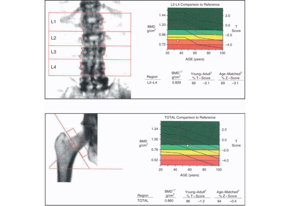
Figure 28.5 DEX Ascan.
Structured oral examination question 6#
Bone scanning
What are the principles of bone scanning? How does a bone scan work?
Bone scan involves the intravenous injection of 99mT -MDP (technetium methylene diphosphonate compound). The technetium gets adsorbed onto the hydroxyapatite crystals in bone and emits gamma rays, which are then received using a scintillation g amma camera. The gamma camera contains sodium iodide crystals, which absorb 99mT gamma rays. The received signal is amplified using photomultiplier tubes and processed using a computer to produce an image. It reflects blood flow and osteoblastic activity . Some features of 99mT-MDP that could be asked by the examiners: (1) Half-life: 6 hours. (2) Excretion: urine – 70% of the administered dose is excreted within 24 hours. (3) Dose: 500–600 MBq. (4) Emits only gamma rays (not alpha or beta).
What is a SPECT scan and give any uses.
Single photon emission tomography involves obtaining tomographic images on a bone scan. The scans are obtained with an arc of 360° around the patient The images can then be reconstructed in axial, coronal and sagift al planes. The SPECT scan is especially useful to study the posterior spinal elements and to look for areas of decreased uptake in osteonecrosis. Sequential imaging with SPECT and CT with the patient in the same position can provide increased diagnostic accuracy by allowing fusion of the anatomical images.11
What is PET scan and what is it used for?
A positron emission scan is mainly used for tumour diagnosis. It involves injection of 18F fluoro-2-deoxy-glucose (FDG), which is a glucose analogue. Half-life: 110 minutes. FDG is transported into cells in a method similar to that of glucose but is not metabolized. Hence it accumulates in areas of high metabolic activity . Successful chemotherapy can cause a decrease in uptake compared to scans before starting chemother apy.1
What is the duration for which a bone scan can be positive following a fracture?
The bone scan usually becomes positive within 24 hours–3 days following a fracture. The dynamic flow component can remain positive foras longas 2–3 weeks following the fracture before returning to normal. The blood pool scan remains positive for approximately 8 weeks. The delayed static sc an is usually positive for 6 months–2 years due to continuing bone healing and remodelling. In cases of malunion, it can remain positive indefinitely due to continued bone remodelling.
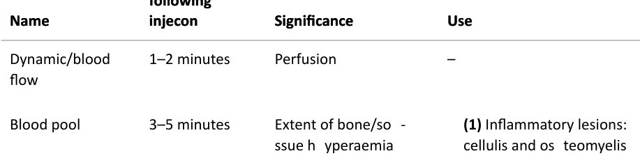
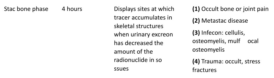
What are the phases of a bone scan?
Timing following injection Significance Use Name
Timing following injection Significance Use
(2) Vascular soft -tissue abnormalities such as tumours
(3) Dating of traumatic lesions such as fractures or myositis ossificans
(5) Tumour: osteoid osteoma and osteoblastoma, especially spine
(6) Primary malignant bone tumours, benign bone tumours
(7) Painful joint arthroplasty
(8) Avascular necrosis
(9) Paget’s disease
Delayed 24 hours – –
What is a ‘flare phenomenon’ in bone scan?
The paradoxical increase in uptake and size on bone scan following chemotherapy for metastatic lesions, despite clinical improvement. This can last for up to 6 months following commencement of chemotherapy. This occurs as a result of bone repair following successful chemotherapy.
Why is a bone scan not the best investigation to study the extent of a bone tumour?
The malignant neoplastic lesions may show increased uptake beyond the actual extent of the tumour due to the presence of hyperaemia and bone oedema occurring beyond the actual extent of the tumour. [ N B : Bone scans can be false negative in up to 50% of cases of multiple myeloma.]
How does 67gallium localize insites of infection?
No clue. Answer: Gallium localizes infection duet o the following factors: (1) Gallium is taken up by neutrophils as well as bacteria. (2) Binding to lactoferrin/plasma transferrin. (3) Increased vascularity. (4) Increased capillary permeability.
What advice will you give the patient after a bone scan?
(1) Drink plenty of fluids for the rest of the day and go to the toilet often. Flush the toilet twice. (2) Avoid contact with pregnant women. (3) If travelling abroad in the 7 days following the scan, take a doctor’s note along asports and airports have very sensitive radiation detectors which may pickup tiny amounts of radioactivity remaining after the scan.
This is a bone scan of apa tien t with a painful hip arthroplasty. What do you think (Figures 28.6a and b)?
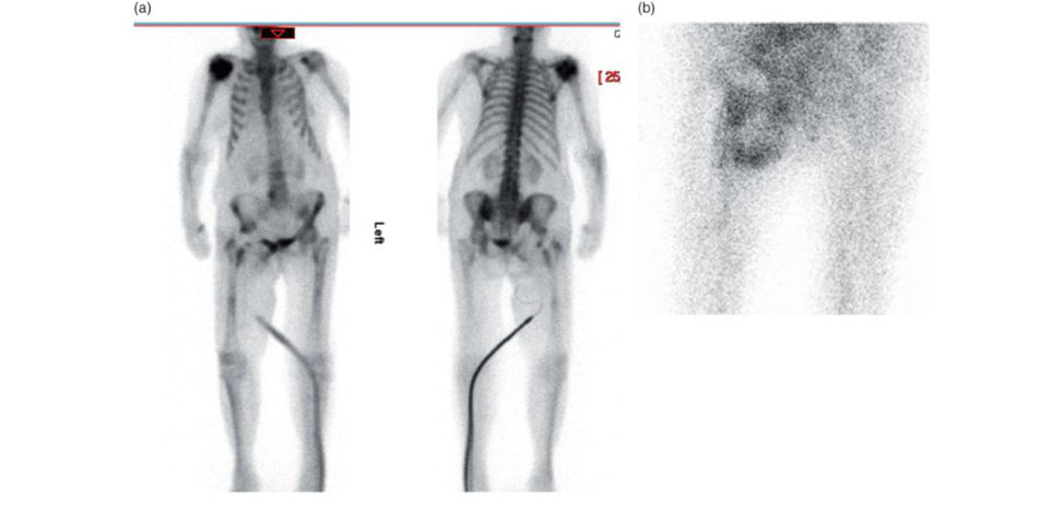
Figure 28.6 The hypervascular abnormality seen on images is suggestive of a soft -tissue abscess with a necrotic centre, possibly related to infection of the right hip prosthesis.
The bone scan images are abnormal. They show a large area of intense hypervascularity at the medial aspect of the right proximal femur suggestive of possible infection or gross aseptic loosening.
Describe the role of a bone scan in the investigations for a painful arthroplasty.
In cases of cemented hip and knee replacements, the bone scan can remain positive for up to 1 year following the operation. In the case of an uncemented THR, there can be increased uptake around the distal tip of the femoral stem for many years postoperatively. The reactive bone uptake in total knee replacement may persist up to 36 months after surgery. Painful arthroplasty, more than 1-year postoperative: In case of suspected periprosthetic infection with radiographs showing no evidence of loosening, a bone scan generally shows an increased uptake in the delayed static phase as well as hypervascularity in the flow and blood pool phases. Mechanical loosening: a bone scan shows increased uptake in the region of loosening in the delayed bone phase due to the increased bone turnover. Blood flow and blood pool phases are normal. Although a technetium bone sc an is sensitive for diagnosing infection, it is not specific. Gallium- and indium-labelled WBC scans are more specific for infection.
Structured oral examination question 7#
Nerve conduction studies
What are nerve conduction studies?
Nerve conduction studies examine the electrical function of nerves and muscles. They can detect loss of axons by looking at the amplitude of the responses and loss of myelin by looking at the conduction velocity of the responses.
How are they performed?
Sensory studies are performed by placing recording electrodes over the course of the nerve and stimulating it. The sensory responses are called SNAPs (sensory action potentials) ( Figure 28.7). Motor studies are also performed by stimulating the nerve but the signals are picked up over the muscles. Their responses are called CMAPs (compound muscle action potentials) ( Figure 28.8). EM Gis performed with a fine concentric needle (a needle within a needle to record the potential difference). Here, the extensor digitorum communis (EDC) muscle is being assessed (Figure 28.9).
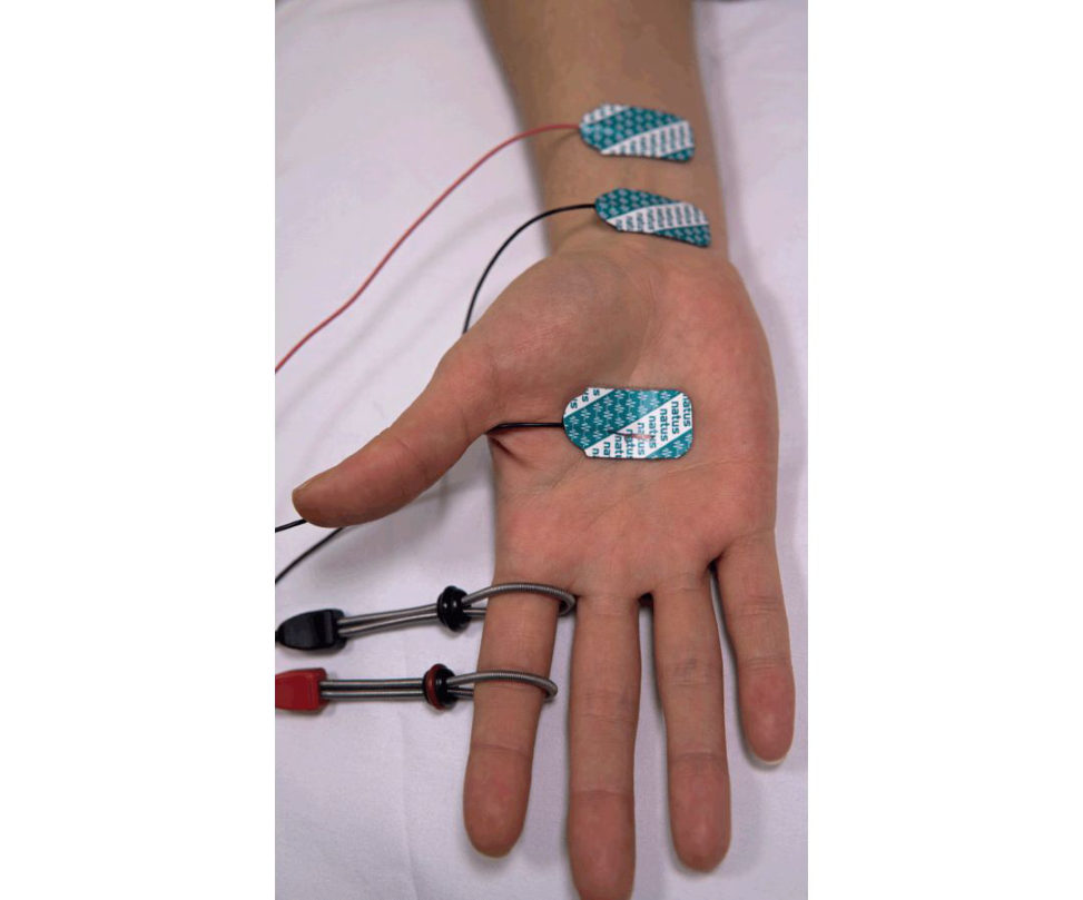
Figure 28.7 Sensory testing orthodromic stimulation using ring electrodes) of the median innervated digit II.
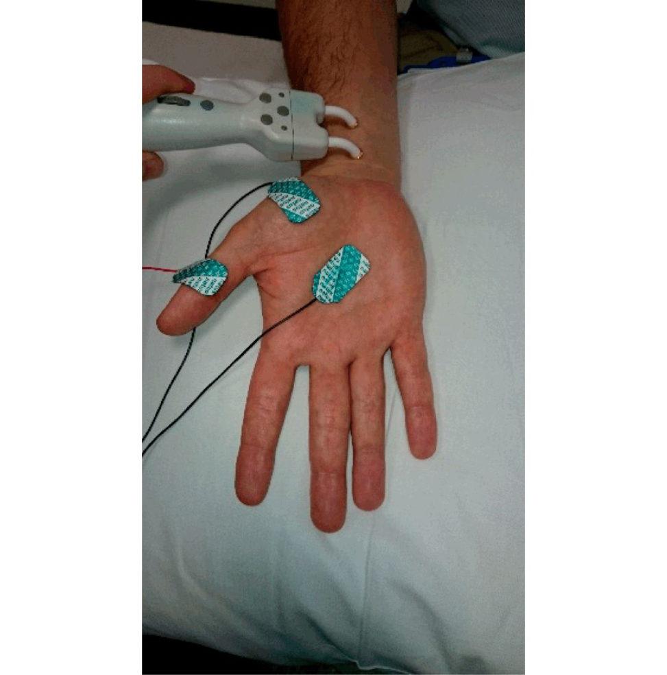
Figure 28.8 Motor testing of the median innervated abductor pollicis brevis (APB) muscle.
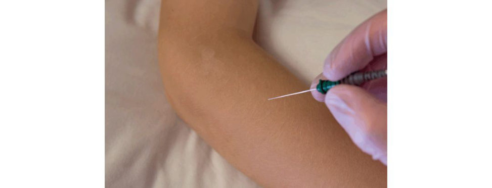
Figure 28.9 EMG studies.
Why are the SNAPs so important and draw the anatomy.
SNAPs determine whether a nerve lesion is post-ganglionic (i.e. a peripheral neuropathy) when they are reduced or preganglionic when they are normal (i.e. radiculopathy, polio, motor neuron disease, etc. and some very exceptional neuropathic disorders). The reason for this is that NCS test the circuitry of nerves up to their cell body. Because the dorsal root ganglion (DR Gis the cell body of the peripheral nerves, and is located outside of the intervertebral foramina, they tend to be spared from radicular compression, even if their dorsal roots are compressed (Figure 28.10). Hence, the SNAPs will be unaffected, even though the patient is experiencing numbness.
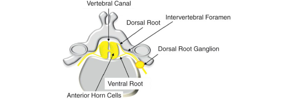
Figure 28.10 Cross-sectional arrangement of dorsal root ganglion.
Structured oral examination question 8#
Nerve conduction studies
Tell me some of the uses of nerve conduction studies? What are the indications for nerve conduction studies?
Nerve conduction studies (NCS) are used to assess peripheral nerves. The most common indications are for assessing focal entrapment neuropathies such as carpal tunnel and cubital tunnel lesions. NCS provide an electrical map of large myelinated nerve function and can therefore be used to determine: (1) The presence and severity of peripheral nerve dysfunction. (2) Whether it is axonal or demyelinating. (3) Localization and distribution. (4) Clues to the underlying aetiology . (5) Prognosis.
What is latency, amplitude and conduction velocity?
Latency = time between the stimulus discharge and the onset of response in milliseconds. Amplitude = size of the response. For sensory nerves, this is in microvolts (millionths of a volt) and for motor nerves this is in millivolts (thousandths of a volt). These are usually measured from baseline to negative peak (by convention is displayed upright, see the diagram below). Conduction velocity (m/s) = is a simple calculation of distance the impulse has travelled divided by the time it has taken to do so. For sensory nerves where stimulation and recording are directly over the nerve, this is the distance between the stimulation site and the recording site (mm) and divided by the time for signal transmission (ms) (Figure 28.11). For motor studies, this is alit ile more complex as while stimulation iso ver the nerve, the signal is recorded over the corresponding muscle. This will therefore include not only the time taken for the current topass along the nerve, but also the time taken for neuromuscular transmission and then muscle membrane depolarization and contraction. Distal motor stimulation is therefore recorded and interpreted as a latency. More proximal stimulation points can provide accurate velocity values once the distal latency is removed. Hence the calculation will be the distance (mm) between proximal and distal stimulating sites / (proximal latency (ms) – distal latency (ms)) (Figure 28.12).
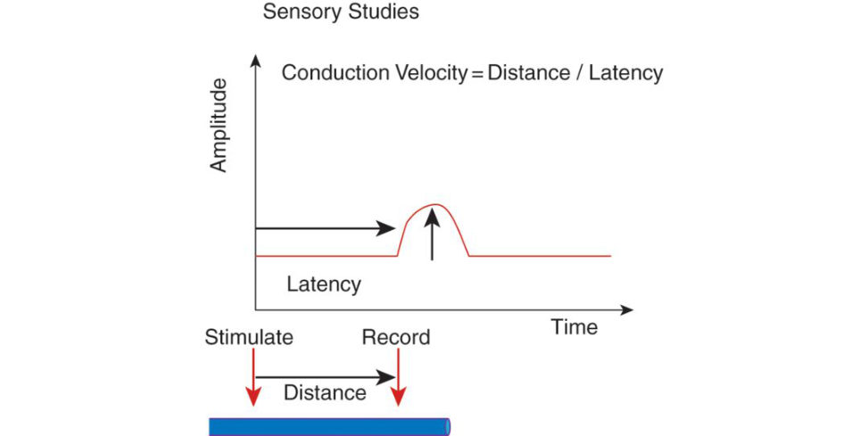
Figure 28.11 Sensory conduction velocity.
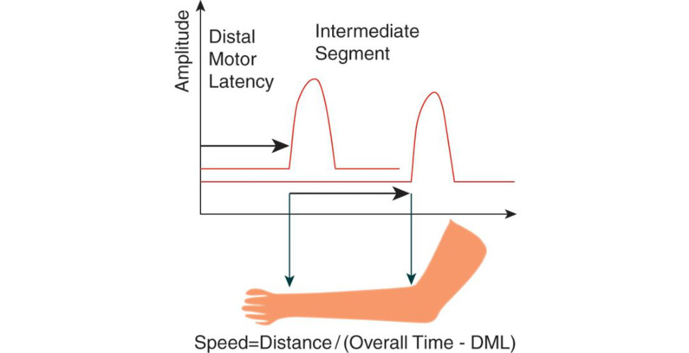
Figure 28.12 Motor conduction velocity.
What is the normal conduction velocity?
Normal conduction velocities in the upper limb are usually around 50–70 m/s and for the lower limb are around 40–50 m/s. Conduction velocities are sensitive to temperature, as cooling slows the velocities Performing NCS in the upper limbs above 32°C is therefore a standard of practice to avoid misdiagnosing conditions such as carpal tunnel syndrome. The degree of myelination isless at birth and so conduction values are about 50% of the adult values, increasing to about 75% by 12 months and 100% by 4–5 years.
What is supramaximal stimulation?
When electrically stimulating the nerve sit is important to ensure that all the nerve fibres are fully stimulated to their maximum response. Failure to ensure this will result in inaccurate readings. It is one of the most common reasons for operator error and can lead to reduced amplitudes and prolonged latencies. Stimulus intensity is incrementally increased until a maximal amplitude is reached and then further increased by a further 20–30% to ensure this. Typical intensities are around 30–40 milliamps.
What are orthodromic and antidromic potentials?
Nerve fibres are designed to transmit their signal in one direction only by voltage and time- gating mechanisms. F or sensory nerves this is from the peripheries toward the central nervous system (CNS). Motor nerves transmit signals from the CNS to the peripheral nerves and then muscles. However, when nerves are externally stimulate das in NCS, depolarization is bidirectional. Orthodromic potentials follow the physiological route, i.e. sensory potentials towards the spinal cord and motor potentials a way from the spinal cord. Antidromic studies (flowing against the physiological direction) can also be performed for sensory potentials. Int heUK, orthodromic responses are preferred in the hands as they provide the most accurate take off latencies which are important for evaluating carpal tunnel. In the feet antidromic studies are preferred as they provide the most accurate amplitudes which are important for assessing peripheral neuropathy. Orthodromic potentials are generally smaller in amplitude but have a cleaner signal definition as only the sensory fibres are stimulated. Antidromic potentials are generally larger amplitude because the sensors are closer to the underlying nerve but are more susceptible to signal artefacts due to co- stimulation of mot or fibres (Figure 28.13).
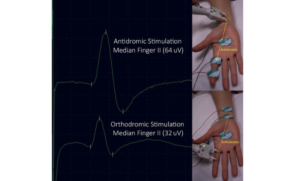
Figure 28.13 Note the difference in amplitude produced by orthodromic and antidromic stimulation.
What are the usual SNAP values you would expect to see in a healthy individual and is there an easy way to remember them?
If one takes an average build 40-year-old, the minimal SNAP amplitudes will be 5, 10, 15 microvolts for the ulnar, median and radial responses respectively, and 5 and 10 microvolts for the superficial peroneal and sural SNAPs. One can double these for a 20-year-old and halve these for an 80-year-old. The minimal velocities will be roughly 50 m/s at 40, a bit faster at the age of 20 (55 m/s) and a bit slower at the age of 80 (45 m/s) (Table 28.1). In addition, no side should be less than 50% of the contralateral side. Table 28.1 SNAP values.
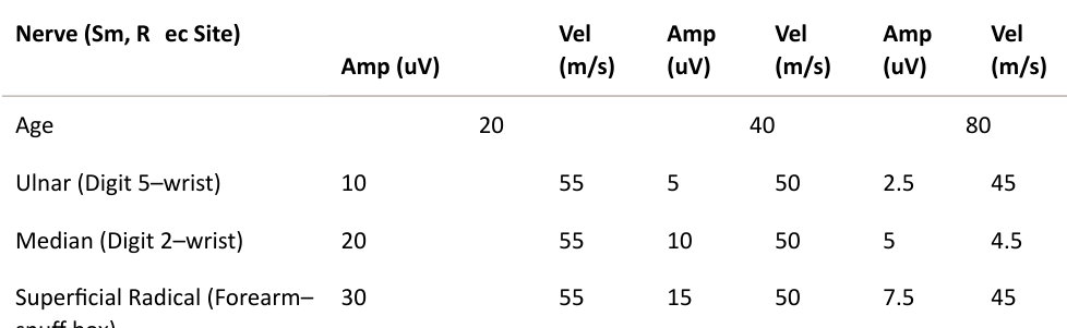
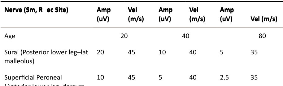
Superficial Peroneal (Anterior lower leg–dorsum ankle)
What are the typical values of CMAPs?
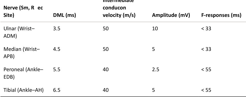
For a typical 40-year-old person, the following values would be expected (Table 28.2). In contrast to the sensory response, there is more variability from overall muscular build, hence a person with a small hand may have a smaller ADM amplitude of around 6–7 mV and a strapping builder would be expected to have a larger ADM amplitude of around 13–15 mV. A 50% asymmetry in amplitude will also be abnormal. Further variation will depend on age and height. With increasing age, amplitudes become smaller. Distal motor latencies (DM Land F-waves increase, i.e. prolong, with age and height, and intermediate conduction velocity will reduce with cooling (and therefore age and height as well). Table 28.2 CMAP values.
What are F-waves?
Electrical stimulation of a peripheral nerve causes depolarization in both directions (orthodromic and antidromic) (Figure 28.14). The antidromic passage of current will enter up into the anterior horn cells and irritate a small percentage of them. This causes a secondary orthodromic response to be generated by them down to the muscles. These are small responses which tend to be around 10% of the motor amplitude and are termed F-waves (so-called because they were first described in the feet but are also present in the hands).
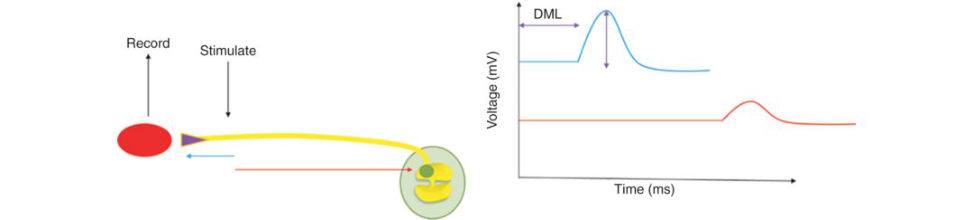
They are measured as a latency (ms) and reflect conduction across the entire motor pathway (up and down). They are therefore proportional to limb length and typical values should not exceed
33 ms in the upper limbs and 55 ms in the lower limbs for average height individuals. F-waves are not a reflex as they only travel in the α motor fibres and do not involve any sensory fibres.
Significance:
(1) Evaluation of proximal (nerve root/plexus/proximal segment) lesions of peripheral nerves.
(2) Early loss of these in Guillain–Barré Syndrome where demyelination often commences in the nerveroots.
(3) Radiculopathy (C8/T1 and L5/S1).
Here are two examples of F-waves from the ulnar nerve (Figure 28.15). The first one shows normal latencies of 30 ms (notice how they are much smaller than the direct muscle activ ation/M-w ave).
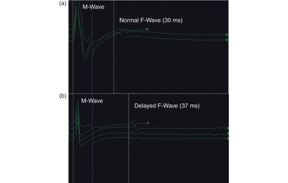
The second shows delayed latencies which were secondary to a cubital tunnel lesion.
Figure 28.14 F-waves.
Figure 28.15 Latent responses. (a) F-waves, (b) normal delayed.
What is the ‘H’ reflex?
Named eponymously after Hoffmann (who worked for Erb). This is a true reflex whereby a selective stimulation of the 1a muscle spindle sensory afferent fibres will activate a monosynaptic spinal cord reflex causing contraction of the corresponding muscle. This requires submaximal stimulation of the mixed nerve. It is the neurophysiological equivalent of an ankle jerk and is only routinely studied in the tibial innervated soleus muscle (Figure 28.16). The clinical application of H reflex: (1) In cases of unilateral sciatica, it helps to differentiate S1 (unilateral abnormality of soleus H reflex) from an L5 radiculopathy. (2) In evaluation of dem yelinating neur opathies (early loss in Guillain–Barré Syndrome). (3) Demonstrating that reflexes are intact when otherwise difficult to obtain clinically, e.g. the elderly.
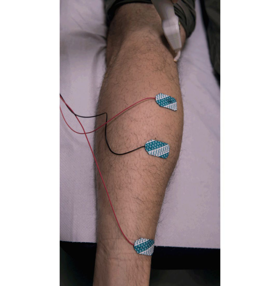
Figure 28.16 Here you can see the tibial nerve being stimulate dat the popliteal fossa and the recording electrodes are placed over the soleus and the Achilles tendon (a ground electrode is placed between the stimulation and recording electrodes to reduce artefact).
How does H-reflex differ from the direct motor or M-wave?
(1) To achieve an H-reflex the sensory fibres need to be selectively stimulate dat low intensity. Initially , there are no direct motor responses from direct orthodromic stimulation (M-responses = CMAPs), only via the H-reflex (Figure 28.17a). (2) As stimulation increases, the direct M-wave will appear. However, there will be collision of impulses from the now activated motor fibres (ascending antidromically) which will arrest and diminish the H-reflex (Figure 28.17b). When the motor response becomes maximal, the H-reflex disappears and is replaced by a small late motor response, the F-wave.
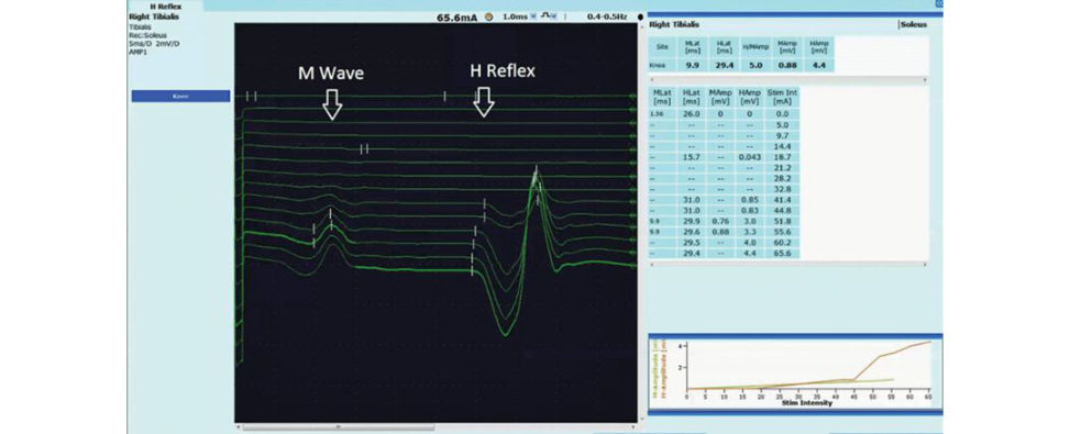
(3) Hence, H-reflexes are present at low stimulation and decrease with increasing stimulation and their amplitudes are relatively higher than M-waves for low-intensity stimuli.
(4) H-reflexes are proportional to height and for an average height individual of 170 cm should be less than 33 ms.
(5) After the age of 1 year, the H-reflex tends to persist only in the calf muscle and FCR
(flexor carpi radialis).
Figure 28.17a H-reflex.
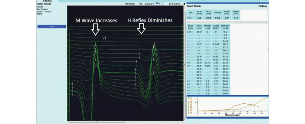
Figure 28.17b Diminished H-reflex.
Structured oral examination question 9#
EMG
Describe ‘endplate activity ’ on EMG.
A healthy muscle should be silent at rest. However, if the EMG needle is inserted into the ‘endplate’ region, i.e. the point where the neuromuscular junctions (NMJs) are located, two types of activity can be detected. (1) Spontaneous release/leakage of acetylcholine from the NMJs leading to non- propagating contraction of parts of some of the muscle fibres. (2) Direct irritation of the NMJs leading to some release of acetylcholine. Because the release of acetylcholine is so small, it is insufficient to depolarize the entire muscle fibre, and these are known as ‘muscle endplate potentials ’. The neurophysiologist must be able to distinguish these from pathological spontaneous activity such as fibrillations by the following characteristics: Endplate noise: small, high-frequency, negative monophasic potentials which sound like seashells. Endplate spikes: small, biphasic and fire irregularly at high frequency and have a crackling sound. These are believed to be caused by needle irritation of the NMJ . Both of these usually occur together and the neurophysiologist will usually first be alerted by the pa tientas these sites of insertion are often quite painful in contrast to other regions of muscle tissue where EM Gis usually painless. Adjustment of the needle’s position will cease the discomfort and these activities.
What is ‘insertional ’ activity on EMG?
When an EMG needle is inserted into a muscle it causes a brief period of irritation leading to a brief burst of activity lasting up to 300 ms and is called ‘insertional ’ activity . In Figure 28.18, the needle was just inserted and was followed by sustained elctrical activity with the patient at rest lasting around 700 ms (100 ms is shown here). Increase: Any cause of muscle membrane irritability – either from a myopathy/myositis or in the very acute stages of a neuropathy. Decrease: Chronic denervation where muscle fibres have been replaced by fibrose dor fatiy tissues.
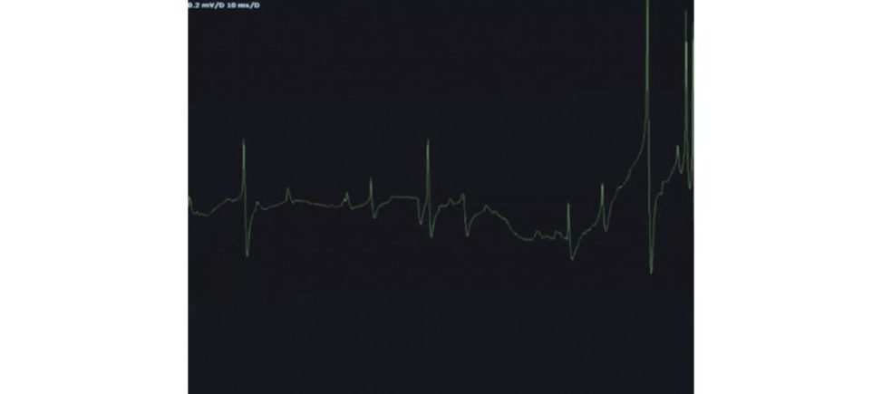
Figure 28.18 Insertional activity on EMG.
Name some of the types of ‘spontaneous’ activity found in a relaxed muscle.
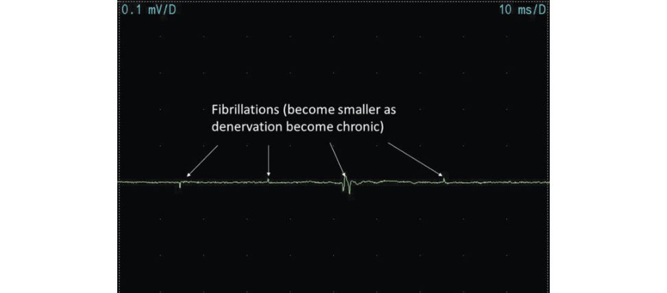
Any activity in a relaxed muscle that lasts longer than physiological insertional activity (i.e. 300 ms) AND is outside of an endplate zone isabnormal and is called ‘spontaneous’ activity . Types: 1. Fibrillations: a. Action potentials that arise spontaneously from single muscle fibres. b. Rhythmic regular firing (their hallmark) which eventually slows and becomes duller over several seconds. c. Biphasic or triphasic (initial positive spiked. When abundant, they sound like ‘raindrops on a tin r oof’. e. Present in both myopathic and neuropathic pathologies. f. In denervation, the y are thought to be caused by secondary upregulation of A Ch- receptors, leading to an increased probability of local depolarization. g. In myopathies, they are thought to arise from leaky muscle membranes, again leading to increased probability of local depolarization. h. In the upper limbs they take at least 14 days to appear and in the lower limbs 21 days, following denervation. i. As conditions become chronic, they diminish in amplitude (Figure 28.19). 2. Positive sharp waves (Figure 28.20): a. These equate to fibrillations.
b. Initial positive phase followed by a slow prolonged phase leading to a duller popping sound (see example).
c. Thought to differ from fibrillations in that the EMG needle may slightly deform the muscle membrane, making it unexcitable and so altering the morphology of the discharge. Movement of the EMG needle can switch the appearances to fibrillations.
d. Sometimes seen prior to fibrillations but usually coexist.
e. Arise from single fibres.
f. Biphasic or triphasic.
3. Fasciculation potentials:
a. Spontaneous single discharges of a group of muscle fibres representing part/whole of a motor unit and the source can be generated anywhere along it. In contrast to fibrillations, the y do not arise from muscle pathologies.
b. Characteristic sound similar to ‘popcorn’ and tend to occur individually. This characteristic differentiates them from voluntary activity which occurs astrains of activity running a t a frequency of at least 5 Hz. You can see this in Figure 28.21 with only a single motor unit visible on the screen.
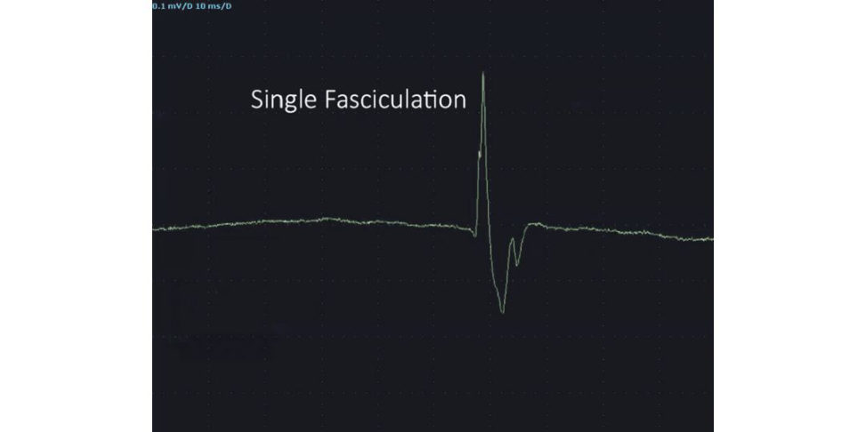
c. Fasciculations are usually visible as twitches. EM Gis particularly useful inlooking for subtle or subclinical fasciculations.
d. They can occur in benign fasciculation syndrome, but also in any denervating process
– and are a characteristic feature of anterior horn cell disease.
4. Myokymic discharges.
a. Group fasciculation potentials resulting from discharge of the same motor unit (Figure
28.22).
b. Characteristic sound of ‘marching soldiers’.
c. Most important use is in differentiating r adiation-induced ple xopathy from tumour infiltration of the plexus, as they are a hallmark of radiation damage.
d. Can be found in any denervating condition.
5. Complex repetiv e discharges.
a. These result from a circus movement of spontaneous discharges activating adjacent muscle tissues.
b. These often abruptly start and stop and have an ‘engine’- or ‘motor’-like sound due to their cyclic nature.
c. Because they need adjacent muscles to be in a state of disrepair to allow pathological spread of the currents (either neurogenic or myopathic causes) they tend to beseen in chronic states only, where fibre type grouping of muscle tissues has occurred.
d. In the example in Figure 28.23, you can see just how regular these are firing and some of the preceding discharges are visibly rastered beneath at the same frequency.
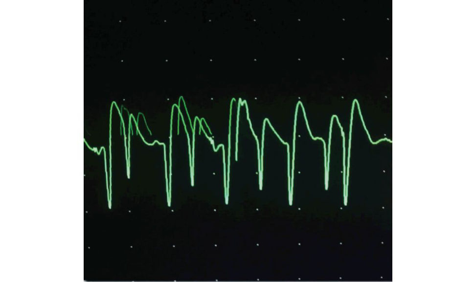
Figure 28.19 Fibrillations diminishing as denervation becomes chronic.
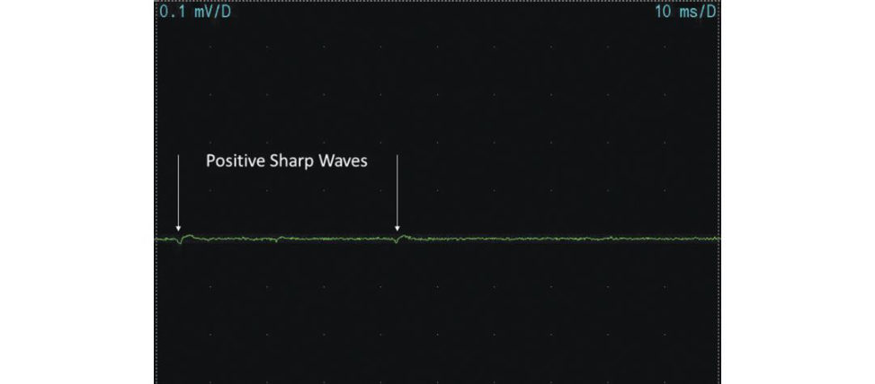
Figure 28.20 Positive sharp waves.
Figure 28.21 Single fasciculations.
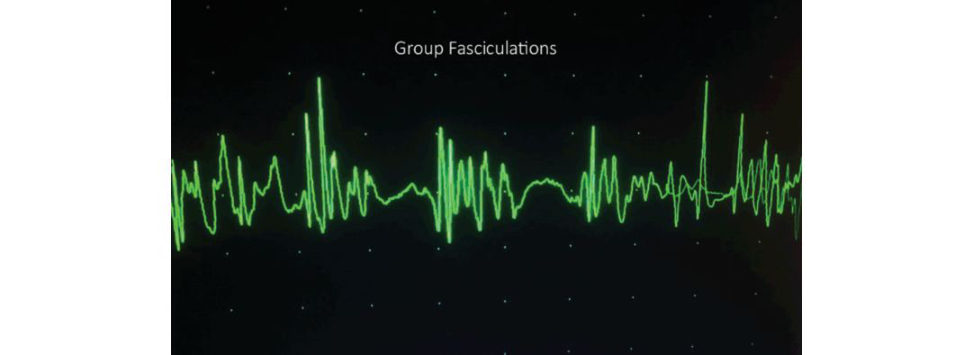
Figure 28.22 Group fasciculations.
Figure 28.23 Complex repetiv e discharges.
Structured oral examination question 10#
Motor action potential
Draw and describe a motor unit action potential.
MU APis the summated electrical activity of the muscle fibres innervated by a single motor neuron. It is generally biphasic or triphasic (see Figure 28.24). In health, they make a sharp and crisp sound.
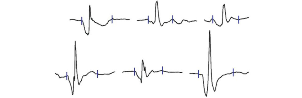
Figure 28.24 Motor unit action potential.
Describe and explain the EMG findings in myopathy.
The electrical characteristics of MU AP sare proportional to the size of the muscle fibres generating them. In myopathies, the fibres shrink, leading to small-amplitude MUAPs. In addition, the density of shrunken fibres increases around the needle insertion site in the muscle so the MUAPS appear small ands pikey (see Figure 28.25). Because the brain is trying to generate force, it attempts to force these shrunken fibres to do so by rapidly recruiting them to contract. Hence, early recruitment and full interference patterns of these smalls pikey units will be present and is the reason why myopathy patients complain of fatigue. Fibrillations/positiv e sharp waves/complex repetiv e discharges may also be present and are a sign of active inflammation, i.e. myositis. In very chronic myopathic conditions, muscle fibre spliting can also cause denervation and so mixed patterns can beseen, e.g. inclusion body myositis.

Figure 28.25 Motor unit action potentials in myopathy.
Describe and explain the EMG findings in neurogenic conditions.
The MUAP configuration will change from the acute to the chronic setings. (1) Very acute seting (first 2–3 weeks) of complete axonal loss there will be no MUAPS and no fibrillations Thereafter, fibrillations will appear and there will be no motor units recruited voluntarily as the brain’s signals will not reach any of the muscle fibres.
(2) More commonly, axonal loss is partial. Again, fibrillations will not be present for the first
2–3 weeks. However, the remaining axons will be able to recruit their muscle fibres, but in a depleted way. Hence, the number of MUAPs visible on the screen (called the interference pattern) will be reduced.
(3) With time nerve regeneration will occur . This will be both locally with terminal sprouting (adjacent nerve fibres growing into denervated muscle fibres) and more proximally, at the site of the nerve lesion.
(4) Local recovery will occur first and results in initially leaky and loose connectivity with those adjacent fibres. This will cause the morphology of the remaining MUAPs to widen and become serrated as those additional fibres become incorporated into that motor unit.
(5) As the innervation becomes increasingly stable and established, the additional serrations (= polyphasia) become increasingly incorporated into the main body of the
MUAP. The MUAP also enlarges as collectively more muscle tissue is generating electrical activity .
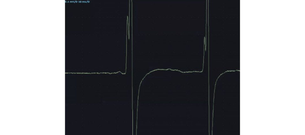
(6) Hence, in chronic denervation, enlarged polyphasic units with reduced interference pattern are present. As regeneration progresses, while they retain their large amplitude, their morphology becomes less complex and their width reduces (Figure 28.26).
Upper motor neuron lesions: will show a reduced recruitment pattern, i.e. a lower firing frequency during maximal contraction ast here isless drive’ to contract the muscles.
Figure 28.26. EMG findings in chronic degeneration.
Structured oral examination question 11#
Nerve conduction studies#
Can you interpret thes eNC Sofa 40-year-old male with tingling in the right radial 3.5 fingers (Table 28.3)?
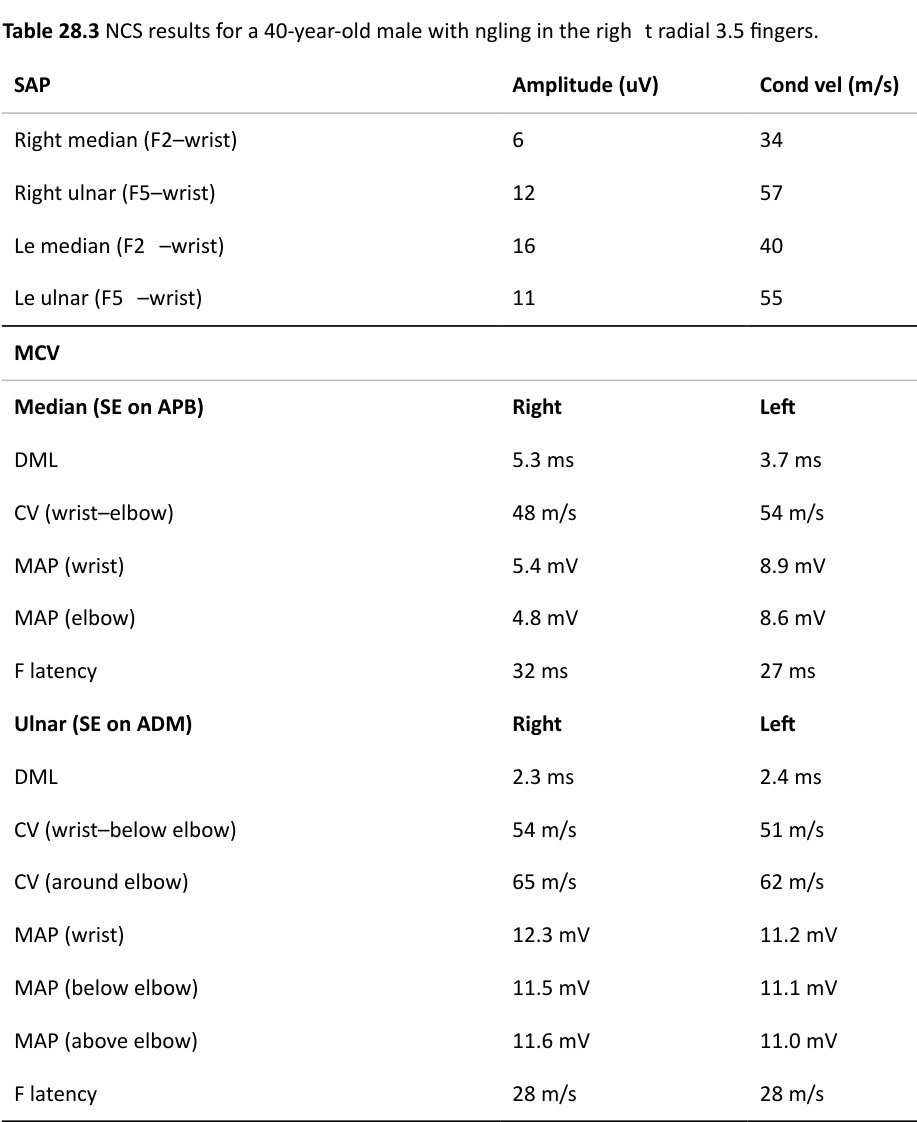
We first analyze the SNAPs to see if this is a pre- or post-ganglionic process. The right F2 is smaller than expected and slower than expected and implies primary demyelination. The right F5 is normal and so there is no evidence of a more widespread neuropathy or brachial plexus lesion. The left F2 is of normal amplitude but is conducting slower than expected. The left F5 is normal.
Therefore, we have bilateral focal median nerve lesions, right more than left, which are demyelinating and in keeping with bilateral carpal tunnel lesions.
Next, we check the MCVs (motor conduction velocities). The DM Lis quite prolonged on the right and the amplitude is asymmetrically smaller than the left. This implies a focal and distal lesion of this nerve, again in keeping with carpal tunnel lesions. Forearm conduction is preserved. The F-wave is prolonged due to the impulse from the anterior horn cells being delayed through the carpal tunnel lesion. Left-sided median motor nerve studies and both ulnar nerve motor studies were normal.
In summary: there is moderate sensory and motor slowing of median fibres on the right and mild and purely sensory slowing of the median fibres on the left. The grades of the carpal tunnel lesions are therefore moderate on the right and mild on the left.
There are two commonly used neurophysiological grading scales for CTS, by Padua12 and Bland13
(Table 28.4). While the precise values of normal and abnormal are different between laboratories, the overall gradings reflect the pattern and degree of fibre involvement. Namely, first the sensory fibres are affected, and this is followed by the motor fibres. For each, the initial loss is of myelin due to the external compression and so the velocities reduce. This is then followed by axonal loss and the amplitudes reduce.
In Figure 28.27 you can see pure sensory fibre conduction slowing (median–digit II) in the green trace compared to the ‘normal’ side in the grey trace. The waveform has shifted towards the right, i.e. is delayed in time. This is the first stage of a carpal tunnel lesion. In this second example (Figure 28.28), you can see distal motor fibre demyelination (median –AP Bin the green trace, compared with the ‘normal’ side in the grey trace. The waveform has also shifted towards the right, i.e. is delayed in time. In addition, the amplitude has slightly diminished and the width of the curve has also increased. This has occurred as more fibres are conducting slowly as they are being compressed. This is a typical finding in a moderate carpal tunnel lesion (Table 28.4).
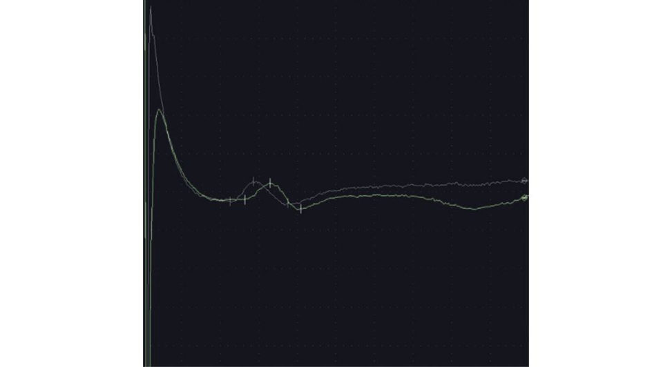
Figure 28.27 Pure sensory fibre conduction slowing.
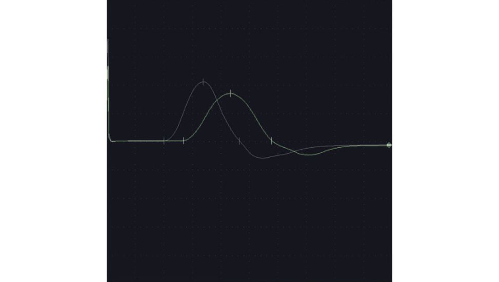
Figure 28.28 Distal motor fibre demyelination.
Table 28.4 Carpal tunnel syndrome grading of severity.
Padua scale (Padua 1997) Canterbury scale (Bland 2000)
Negative Normal findings in all tests Grade 0 Normal Normal findings in all tests
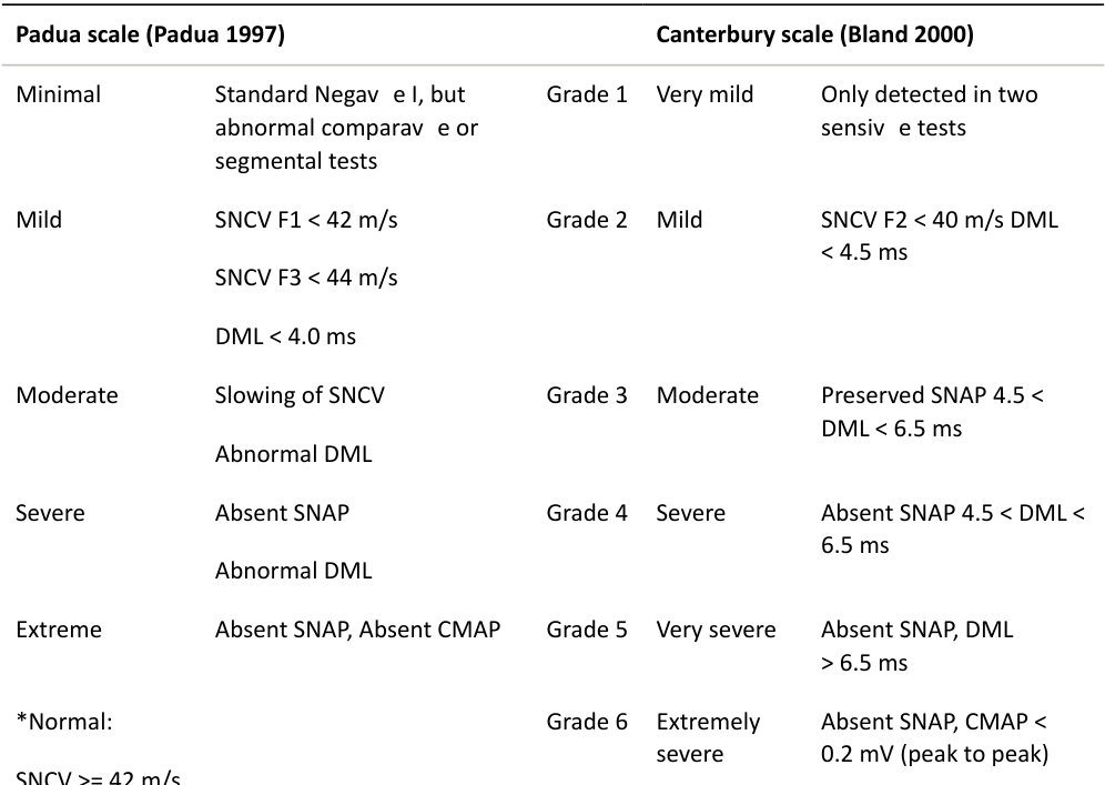
DML < 4 ms
Structured oral examination question 12#
Nerve conduction studies
Can you interpret thes eNC Sofa 40-year-old male with tingling in the right ulnar 1.5 fingers (Table 28.5)?
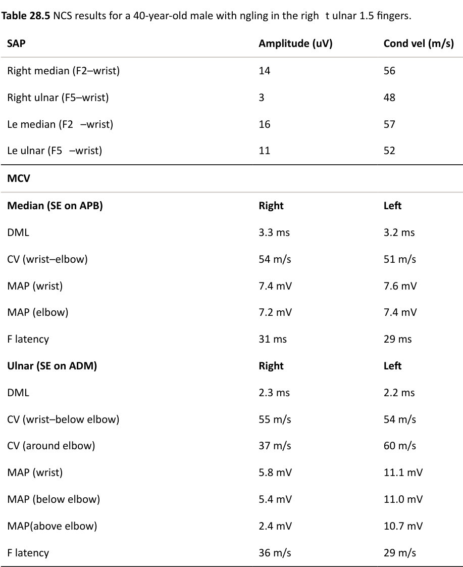
We first analyze the SNAPs to see if this is a pre or postganglionic process. The right F2 SNAP is normal. However, the right F5 is smaller than expected and also asymmetrically reduced compared to that on the left. W e are therefore dealing with a post-ganglionic lesion, involving right ulnar nerve fibres.
Next, we check the MCVs (motor conduction velocities). These are normal for the right median nerve. However, the right ulnar nerve shows conduction slowing across the elbow and some conduction block. This is not present on the left side. The F-w ave is also prolonged as the impulses from the anterior horn cells are being delayed through the cubital tunnel.
In summary: there is moderate motor slowing of the ulnar fibres on the right at the level of the elbow together with a reduced sensory amplitude. These are signs of focal demyelination a t this level which are in keeping with a moderate cubital tunnel lesion.
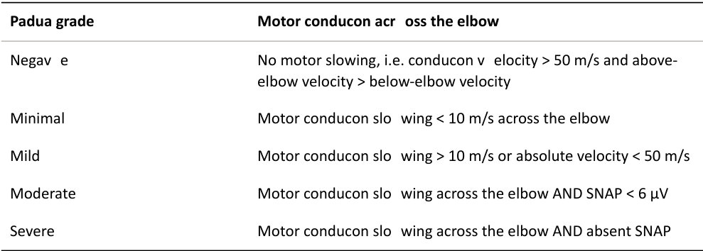
The best-described neurophysiological grading scales for cubital tunnel are from Padua14 (Table
28.6). In contrast to carpal tunnel, the motor fibres tend to be affected first and are followed by the sensory fibres (with rare exceptions and is thought to relate to the orientation of the fibres against the olecranon groove). Initially , the myelin becomes affected and conduction velocity drops due to the external compression. This is then followed by axonal loss with loss of amplitude.
Table 28.6 Padua grading for ulnar nerve compression.
Structured oral examination question 13#
Nerve conduction studies
Can you interpret thes eNC Sofa 20-year-old female with tingling in the right ulnar 1.5 fingers (Table 28.7)?
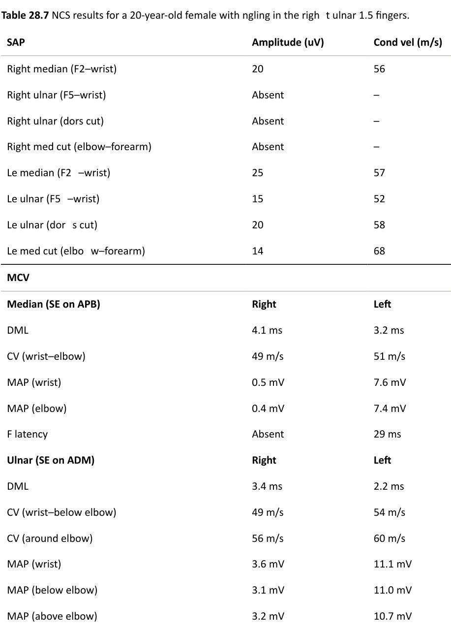
MCV
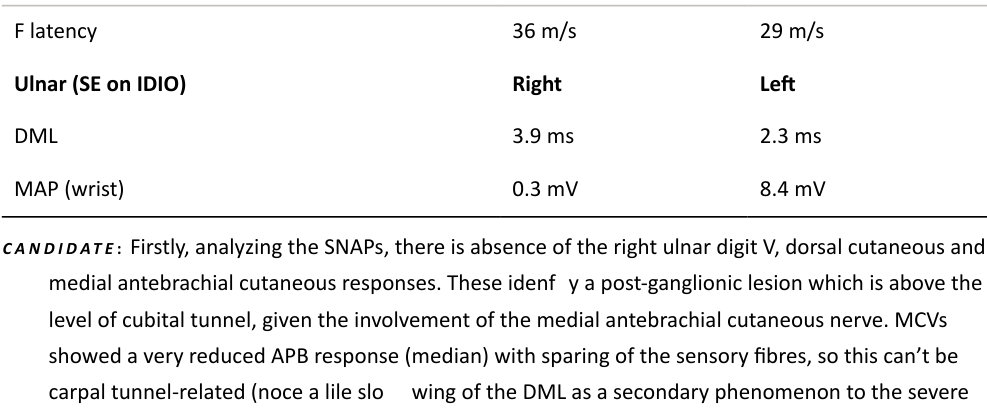
axonal loss). I also see some axonal loss of the ADM muscle, but not as much as the AP Bor IDIO (first dorsal interosseous). These findings are suggestive of a lower trunk plexopathy. I would wish to see the EMG (Table 28.8)
Table 28.8 EMG results.
EMG
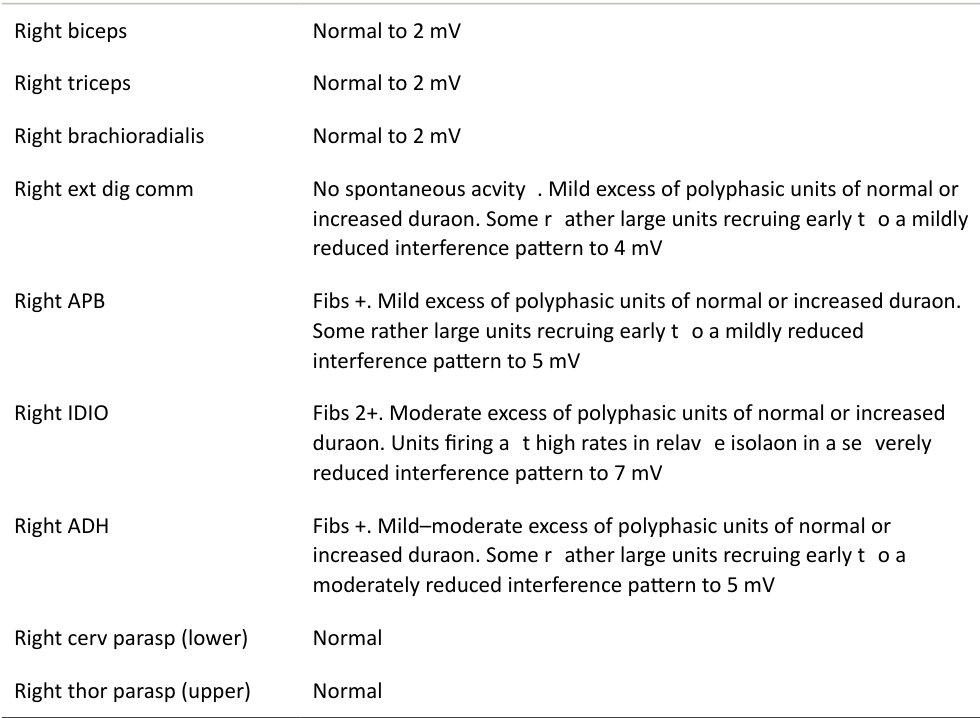
The EMG shows active denervation (fibrillations) with underlying chronic denervation (enlarged, wide, polyphasic units) in the T1–C8 innervated muscles. These are in keeping with the pattern seen in th eNCS findings (APB + FDIO smaller CMAP amplitudes than the ADM). Paraspinal EMG was normal and so excludes the possibility of a superimposed C8/T1 radiculopathy. This combination of sensory and motor axonal denervation is in keeping with a lower trunk brachial plexopathy and at this age, I would consider a thoracic outlet syndrome as the primary differential and arrange for the appropriate imaging. Had this been an 80-year-old patient, I would consider a pancoast tumour as the primary differential.
Structured oral examination question 14#
Nerve conduction studies
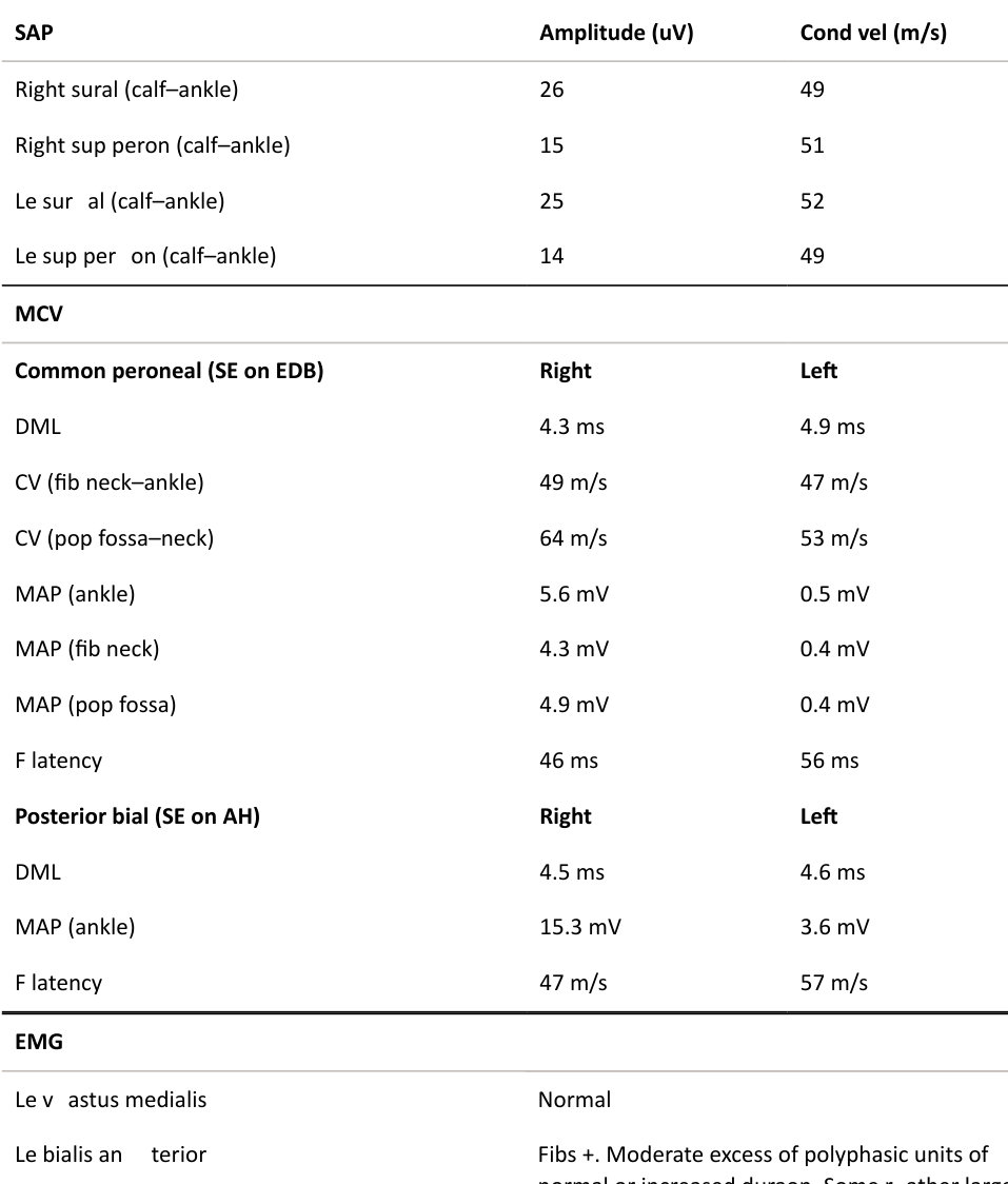
Can you interpret thes eNC Sofa 40-year-old with numbness in the left leg and a foot drop (Table 28.9)? Table 28.9 NCS results for a 40-year-old with numbness in the left leg and a foot drop.
Left tibialis anterior Fibs +. Moderate excess of polyphasic units of normal or increased duration. Some rather large units recruiting early to a moderately reduced interference pattern to 6 mV
EMG
Left gast roc (medial head) Fibs+. Individual units of essentially normal configuration. Some rather large units recruiting early to a moderately reduced interference pattern to 6 mV.
All the sensory responses are normal and so this cannot be due to a peripheral neuropathy. Motor responses show significant reduction in the CMAP s on the left side for both the peroneal-EDB and tibial-AH mot or studies and prolongation of their F-w aves. This suggests a pre-ganglionic lesion. EMG findings corroborate active moderate denervation in the muscles innervated by L5/S1 root levels. The findings are in keeping with an active left L5/S1 r adiculopathy.
Structured oral examination question 15#
Nerve conduction studies
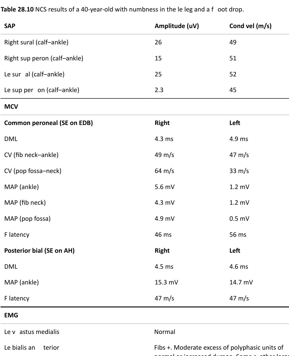
Can you interpret thes eNC Sofa 40-year-old with numbness in the left leg and a foot drop (Table 28.10)?
Left tibialis anterior Fibs +. Moderate excess of polyphasic units of normal or increased duration. Some rather large units recruiting early to a moderately reduced interference pattern to 6 mV.
EMG
Left tibialis posterior Normal
The left superficial sensory SNAP is reduced and suggests a post-ganglionic lesion. Motor responses show slowing of motor conduction of the left peroneal nerve across the fibula neck. The F- wave is also prolonged as the signal is passing through the demyelinated zone. EMG confirms moderate active denervation in the tibialis anterior muscle. Absence of denervation in the tibialis posterior muscle excludes a sciatic lesion or L5 r adiculopathy. The findings are in keeping with a moderate active left peroneal nerve lesion across the fibular neck.
Notes
1. Ramachandran M. Basic Orthopedic Sciences. London: Hodder Arnold; 2007.
2. Theocharopoulos N, Perisinakis K, Damilakis J, Papadokostakis G, Hadjipavlou A, Gourtsoyiannis N. Occupational exposure from common fluoroscopic projections used in orthopaedic surgery. J Bone Joint Surg Am. 2003;85:1698–1703.
3. Martin DJ, Wells ITP, Goodwin C, Physics of ultrasound. Anaesth Intens Care Med. 2010;16(3):132– 135.
4. Miller MD. Review of Orthopaedics. 5th Edition. Philadephia, PA: Saunders Elsevier; 2008.
5. Einhorn TA, O’Keefe RJ, Buckwalter JA (Eds.). Orthopaedic Basic Science: Foundations of Clinical Practice. 3rd edition. Rosemont, IL: American Academy of Orthopaedic Surgeons; 2007.
6. Burch J, RiceS, Yang H, et al. Systematic review of the use of bone turnover markers for monitoring the response to osteoporosis treatment: the secondary prevention of fractures, and primary prevention of fractures in high-risk groups. Health Technol Assess. 2014;18(11):1–180.
7. Sharma U, Stevermer JJ. Bisphosphonate therapy: when not to monitor BMD. J Fam Pract. 2009;58(11):594–596.
8. Kanis JA. Diagnosis of osteoporosis and assessment of fracture risk. Lancet. 2002;359;1929–1936.
9. www.sheffield.ac.uk/FRAX/tool.jsp
10. Singh M, Nagrath AR, Main iPS. Changes in trabecular pattern of the upper end of the femur as an index of osteoporosis. J Bone Joint Surg [Am]. 1970;52A:457–467.
11. Waller M, Chowdhury F. The basic science of nuclear medicine. Orthop Trauma. 2016;30:3,201– 222.
12. Pa duaL, LoMonaco M, Grego riB Valen teEM, Padua R, Tonali P. Neurophysiological classification and sensitivity in 500 carpal tunnel syndrome hands. Acta NeurolS cand. 1997;96(4):211–217.
13. Bland JD. A neurophysiological grading scale for carpal tunnel syndrome. Muscle Nerve. 2000;23(8):1280–1283.
14. Pa duaL, Aprile I, Mazza O, et al. Neurophysiological classification of ulnar entrapment across the elbow. Neurol Sci. 2001;22(1):11–16.